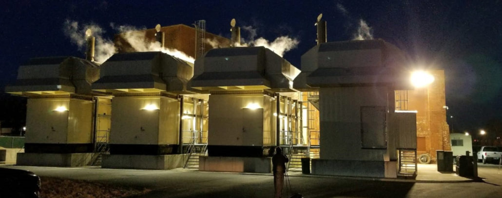
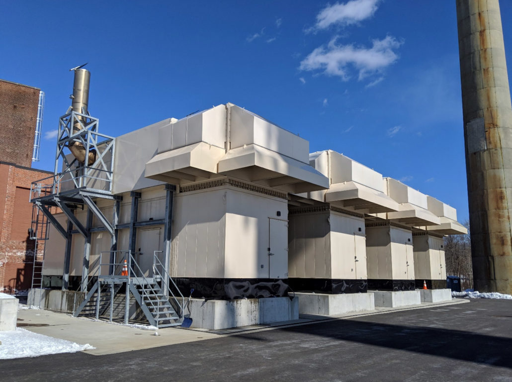
When the Taunton Municipal Light Plant in Taunton, Massachusetts, installed four new 2.5 megawatt generators, the facility’s managers were excited to reap the rewards of their new additions.
The upgraded generators would allow the facility to move to standby power during peak consumption times, reducing energy usage and associated costs and allowing the utility to redeem financial incentives from local power authorities. The upgrade would also reduce the plant’s carbon footprint and help it achieve improved overall performance.
But they had no idea they’d soon be forced to manage a daunting noise control challenge, as well.
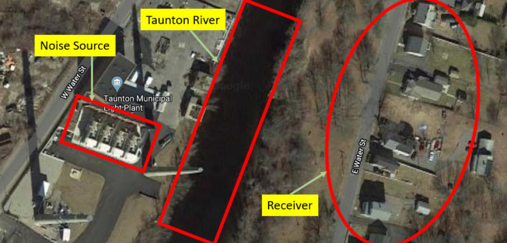
After the generators’ commissioning, residential receptors located near the facility recorded unacceptably high sound levels. The new generator units were found to exceed state noise emission regulations, creating an unexpected liability for the Taunton plant’s managers. They knew they’d need to act fast to address the problem and satisfy local officials.
What happened next was a textbook example of the kind of collaborative innovation that can occur when an acoustic consultant, a facility owner and a noise control specialist team up to develop an effective end-to-end solution to an unexpected sound issue. In this case, our team was called in to provide its extensive expertise and experience, helping the Taunton plant’s leadership group stay focused on their core duties while we managed an unsightly noise problem and helped the facility comply with local ordinances.
The Challenge
Addressing the noise issue with an external acoustic treatment seemed to be the only option at first, given that the generator sets (gensets) were already installed in an acoustically treated enclosure. But that would have necessitated the installation of a 30-foot tall acoustic grade barrier surrounding most of the area footprint. Doing so would have created several challenges including:
- Interfering with traffic accessiblity around the facility, since the barrier wall would have blocked a portion of an adjacent roadway
- Necessitating considerable site remediation and incurring hefty construction costs due to the substantial foundations needed to support a wall of that size
Our team knew there had to be a better solution—so we set out to assess the situation and develop one. In doing so, we embarked on an extensive process of discussions with the acoustic consultant to find a more practical, elegant way to address the problem. Forming the basis of these conversations were several key considerations for the project:
Acoustic Performance—Through the detailed analytical efforts of the acoustic consultant, it was discovered that the acoustic deficiencies were primarily caused by insufficient transmission loss in the enclosure’s casing. This was a result of both inadequate mass to attenuate lower frequencies, and vibratory transmission into the wall panels (which de-rated the existing panel’s transmission loss performance).
Our team was faced with the mammoth task of designing an ’at-source’ solution that would address the shortfall in acoustic performance, while overcoming the major cost and functionality concerns associated with the barrier wall concept. We conducted analytical and computational testing to approximate the de-rated performance of the existing enclosure panel when coupled with vibratory excitation. Next, we needed to calculate the performance of the secondary acoustic panel that would eventually be decoupled off of the existing enclosure. The application area of this at-source approach was then carefully evaluated in the acoustic consultant’s model to target results at the easterly receptors. Tensions mounted as our team knew the slightest miscalculation could compromise the entire project.
Site Fitment—Integrating this type of solution would entail precise field measurements enabling us to work around the various openings and appurtenances affixed to the unit. Given the location of the facility relative to our head office, it was also critical that field re-work be virtually eliminated.
In other words, any solution we provided would need to be a perfect fit for the facility’s site and acoustic requirements.
Time—The project would need to be completed in just six weeks from the initial design phase to full installation. The timeline was dictated by the start of winter, which can limit installation windows due to the typically inclement weather in the area at that time of year. Given the location and operational constraints of the facility, the design approach also needed to minimize time on-site as much as possible.
The Solution
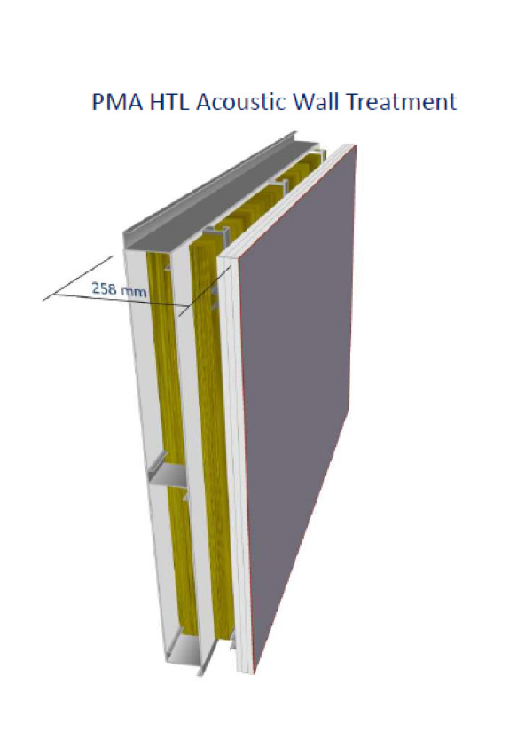
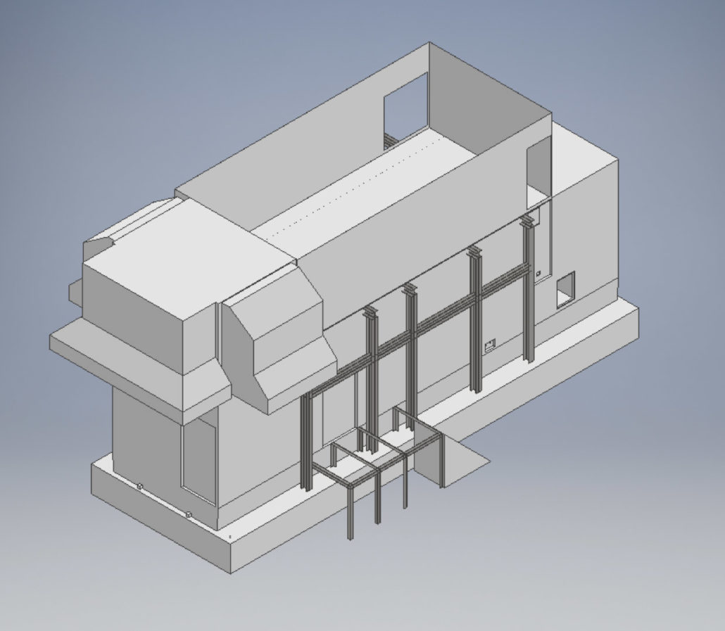
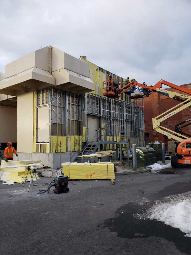
The project team arrived at the final concept: construct a built-up vibration isolated acoustic wall panel onto the east and south wall of the fourth generator. Using a combination of empirical calculation and legacy-free field performance data, we were able to predict the amount of added mass loading and acoustic absorption required to achieve the required attenuation when factoring in a vibratory decoupling mechanism. An external steel stud wall was constructed in front of the existing enclosure, then pinned back to the enclosure structure using a grid of neoprene wall mounts. The new acoustic panel was laid into the decoupled stud wall and finished with an architectural cladding system.
A small acoustic vestibule was added over the main entry door to mitigate breakout noise through the door seals to avoid disruption to any of the system disconnects and other functional componentry.
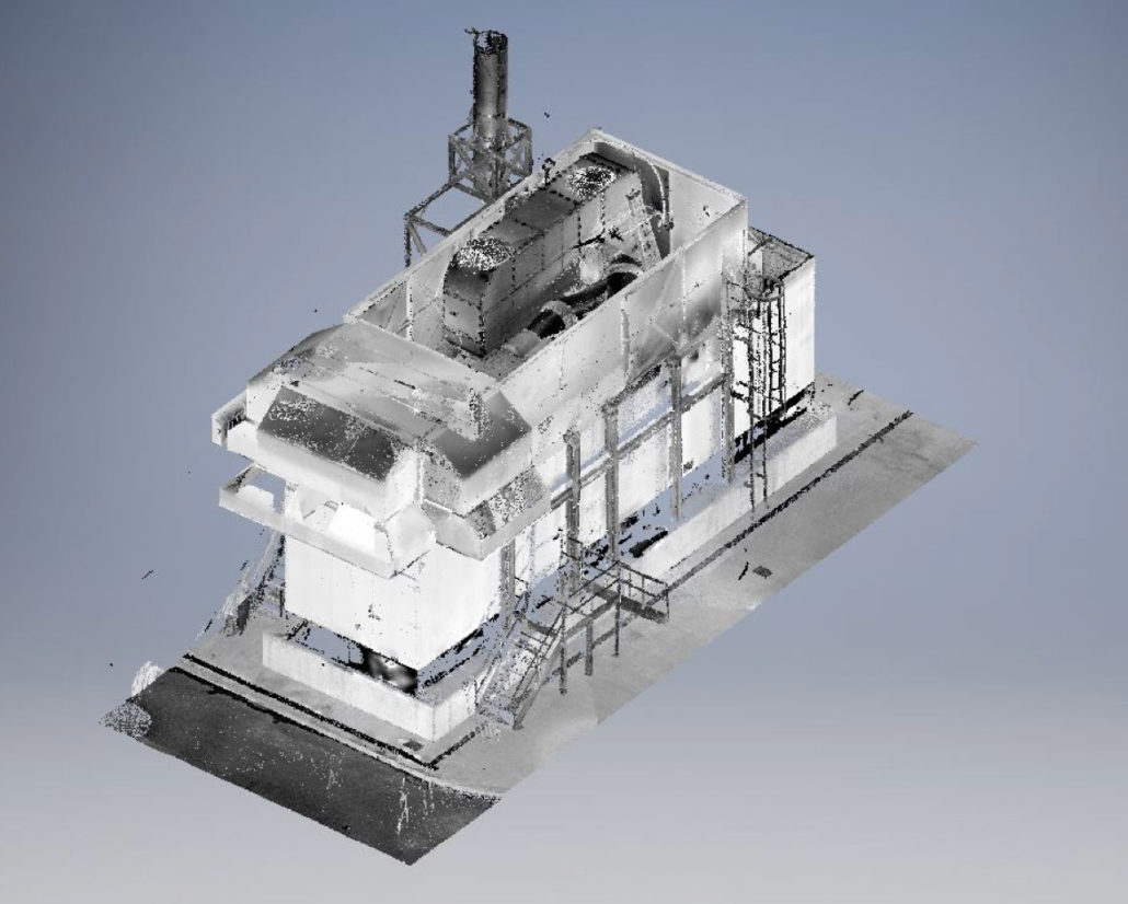
Instead of attempting to manually capture all of the small details on this large system to address the site fitment issues, we used long-range laser scanning to generate a detailed point cloud model of the entire equipment set. This virtually eliminated the need for extensive onsite measurement. All detailed design was completed by Parklane’s in-house engineers and CAD technicians, using the 3D-point cloud model created in this single scanning process.
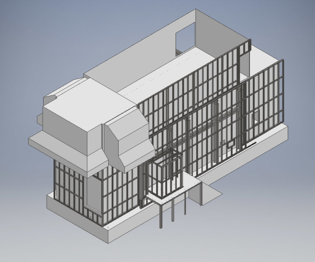
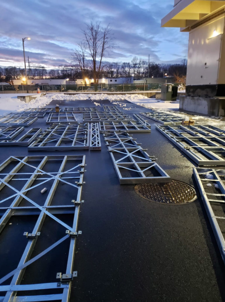
To limit field time, our team manufactured the steel stud wall using a cutting-edge CNC stud forming machine. Our design and manufacturing department quickly learned the interfacing and operational nuances of this complex piece of equipment to produce the necessary material—all in less than a week.
All members were cut, notched, dimpled and labelled to provide rapid on-site assembly. By moving to this lightweight steel stud system, we were able to eliminate a considerable amount of material cost from the design, in addition to eliminating the need for timely on-site field welding during construction.
The Result
By moving to this innovative at-source approach, we avoided the addition of foundations or any major substructure. This alleviated site congestion concerns, and reduced the cost of the project to about 25 per cent from the original proposal.
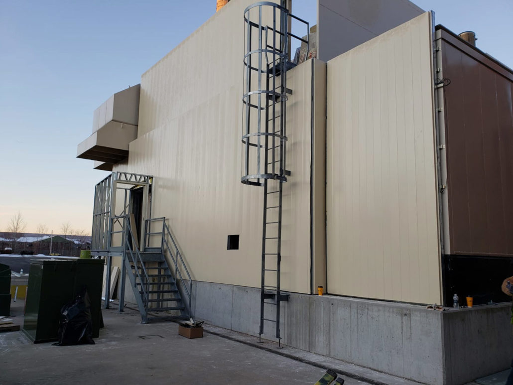
Through extensive collaboration with the acoustic consultant, we were able to successfully reduce the Taunton plant’s noise emissions to within the limits of local ordinances, achieving our project objectives in as unobtrusive and efficient manner as possible. Most importantly, we completed the implementation in 10 consecutive days, with no impact on the plant’s operations.
The client was not only satisfied with the outcome, but was surprised by our rapid turnaround times and ability to design, manufacture and install a noise control solution that was also architecturally appealing and aligned with the facility’s existing aesthetics.
This project was a flagship example of creativity, engineering prowess and collaboration coming together to deliver an ideal project outcome.
The Parklane Team